SDI-150 Laser Gyro Inertial Navigation System
-
Output:
-
500
-
Export Port:
-
beijing
-
Payment:
-
T/T
-
Model NO:
-
SDI-150

- Product Details
- {{item.text}}
Quick Details
SDI-150 Laser Gyro
Inertial Navigation System
Technical Manual
The core inertial sensor of the SDI-150 laser gyro inertial navigation system is composed of a three-axis 50-type laser gyro combined with a three-axis quartz flexible accelerometer. It mainly includes: secondary power supply, navigation computer, current-to-frequency conversion circuit, gyro control board, gyroscope, accelerometer, and mechanical structure, etc.
Main functions
(1) It can provide real-time information on position, heading, horizontal attitude, speed, angular velocity, etc.;
(2) When satellite navigation information is available, it can complete initial alignment while moving;
(3) It has self-inspection and data storage;
(4) It can align with other devices through parameter settings.
Main Technical Specifications and Characteristics
a) Navigation system: strapdown inertial navigation;
b) Preparation time: ≤8s (from power-on to completion of self-inspection);
c) Alignment time: 10min (can be selected as 5min, 10min, 15min);
d) Alignment method: self-alignment;
e) Precision of core components:
- Gyroscope
Zero bias stability: ≤0.01°/h (1σ);
Zero bias repeatability: ≤0.005°/h (1σ);
Scale factor error: ≤10ppm (1σ);
- Accelerometer
Zero bias stability: ≤1×10⁻⁵ g (1σ);
Zero bias repeatability: ≤1×10⁻⁵ g (1σ);
f) Attitude accuracy (precision, pure inertia):
Heading: ≤0.04°secφ (1σ, 1h);
Attitude: ≤0.01° (1σ, 1h);
g) Pure inertial autonomous navigation accuracy
Position error: ≤0.8 nautical miles/hour (CEP);
h) Maximum measurement range
Pitch angle: ±90°;
Heading angle: 0~360°; Roll angle: ±180°;
Pitch and heading angular velocity: ±800°/s;
Roll angular velocity: ±800°/s;
Acceleration: X-axis ±50g; Y-axis ±50g; Z-axis ±50g;
i) Navigation data update rate: ≥100Hz;
j) Voltage input range: 24±2V;
k) Steady-state operating power consumption: ≤18W;
l) Physical parameters
1.Mass: ≤3kg;
2.Physical dimensions: 150 mm×140 mm×113mm;
m) Interface mode: 1 RS-232 and 2 RS-422.
n) Operating temperature: -40℃~+70℃.
Product Composition
The product mainly consists of three 50-type laser gyros, three quartz flexible accelerometers, a gyro control board, an IF conversion module, a navigation computer, a power board, a housing, and shock absorbers. The main components are introduced as follows:
(1) Three-axis Laser Gyro
In each inertial sensing assembly, the three laser gyros are designed in an integrated manner and are orthogonal to each other. Based on the optical Sagnac effect, they are sensitive to the inertial angular motion of the carrier.
(2) Accelerometer Assembly
Each inertial sensing assembly contains three quartz flexible accelerometers that are orthogonal to each other and are used to sense the linear acceleration information of the carrier.
(3) Gyro Control Board
The gyro control board is responsible for powering the resonant cavities of the three-axis laser gyros. It also controls the high voltage, jitter, frequency stabilization, and locking of the laser gyros.
(4) IF Conversion Module
The IF conversion module converts the analog current signals output by the accelerometer into digital pulse frequency signals, ensuring that the inertial information sensed by the inertial measurement is output in digital form.
(5) Navigation Computer
The navigation computer receives data from the gyros, accelerometers, and external GPS to perform combined navigation calculations and outputs navigation information such as position, velocity, and attitude.
(6) Power Board
The power board is mainly used to convert the input DC voltage into various voltages required by the inertial measurement unit for use by different control modules (high voltage, ignition, jitter, and frequency stabilization).
(7) Housing and Shock Absorbers
The housing primarily serves as a support, fixation, and sealing structure. The shock absorbers are responsible for connecting the main body to the outside, isolating the interference from external vibration impacts on the inertial navigation assembly, and also isolating the vibration generated by the inertial navigation assembly from interfering with external equipment.
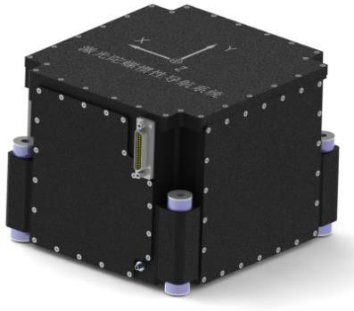
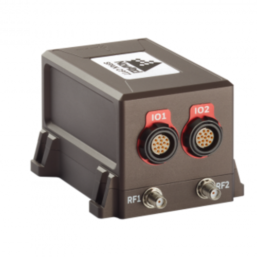
External mechanical interface
The external installation port is shown in the figure. You are advised to use four M5 screws to secure the port.